
Marine Advisory: 18/2026 (Rev. 1) - Nishi-F Co., Ltd Freefall Lifeboat Model: FF-65 (Capacity: 25 persons)
11 August 2026
Marine Advisory 18/2026 (Rev. 1)
7 August 2026
Marine Advisory: 18/2026 Rev.1
(Revokes Marine Advisory: 18/2026)
Subject: Nishi-F Co., Ltd Freefall Lifeboat Model: FF-65 (Capacity: 25 persons)
Reference: (a) Nishi-F Co., Ltd. Letter to Customers dated 21 January 2026 The following changes have been included:
a. Added passage width between driver’s/pilot’s seats
Dear Shipowners/Operators/Masters:
The purpose of this Marine Advisory is to bring to your attention the subject letter issued by NishiF Co., Ltd. (reference (a)), concerning their freefall lifeboat (FFLB) model FF-65 with a capacity of 25 persons manufactured on or after October 2010, and to raise awareness of an interpretation made by some Port State control (PSC) authorities related to the width of the passageway.
Occupants passage width
The letter advises that in some products, it has been confirmed that the clear width of the passage (as shown below) between some of the seats inside the FFLB does not meet the required standard of 480 mm specified in Chapter 4.7.2.1 of the IMO Life-Saving Appliance (LSA) Code at locations (1) and (2) in Attachment 1.
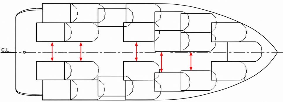
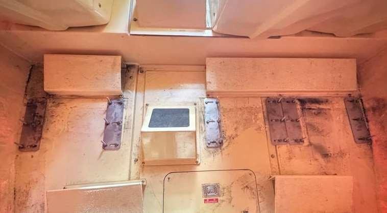
A repair method has been approved by ClassNK, which involves installing adjustment brackets on the seat mounting bolts on both sides of the passage and adjusting the seat position and angle, which will then ensure that the required passage width is met (Refer to Attachment 2 and Attachment 3).
Driver/pilot seats passage width
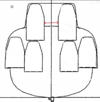
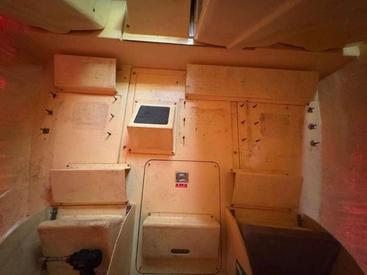
The Administration has become aware that some Port State control (PSC) authorities consider that the passage width of 480 mm should be applied to the passage between the driver/pilot’s seats as shown below.
A. Recommendation to Operators
Nishi-F Co., Ltd Freefall Lifeboat Model: FF-65 (Capacity: 25 persons)
The Administration recommends Shipowners, Operators, and Masters to check if this make and model FFLB is installed on board their vessels, and if affirmative, to contact the manufacturer as noted in reference (a), for an approved rectification plan to meet LSA Code requirements for the clear width of the passage between all seats fitted on the Free-fall lifeboat. The plan shall be executed not later than 1 October 2026.
Recognized Organizations which have issued the Cargo Ship Safety Equipment Certificate to the identified vessels will verify during the next annual/periodical/renewal survey, but not later than 1 October 2027, that appropriate corrective actions have been taken and the FFLBs comply with the LSA Code.
General Recommendations
Regarding FFLBs of other Makes and Models/Types, Shipowners, Operators, and Masters should measure the passage width and contact the Maker/Manufacturer for an approved rectification plan, if the measured passage width is less than 480 mm.
If a more formal/vessel specific authorization letter is needed for additional time to carry out modification, and/or for more information, please contact the Regulations and Standards department at regsandstandards@liscr.com.
* * * * *
Attachment1 Locations with Insufficient Passage Width
1,Passage Width Measurement Locations
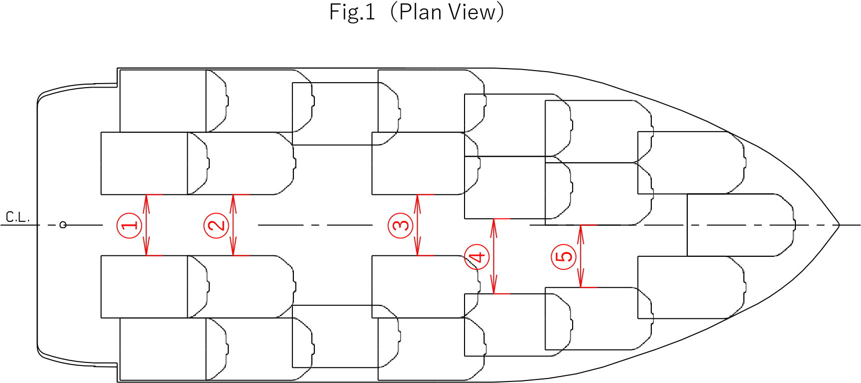
The applicable passage width locations of the free-fall lifeboat (Model FF-65) are indicated as positions
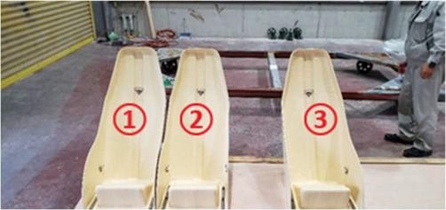
① to ⑤ in Fig. 1 (Plan View).
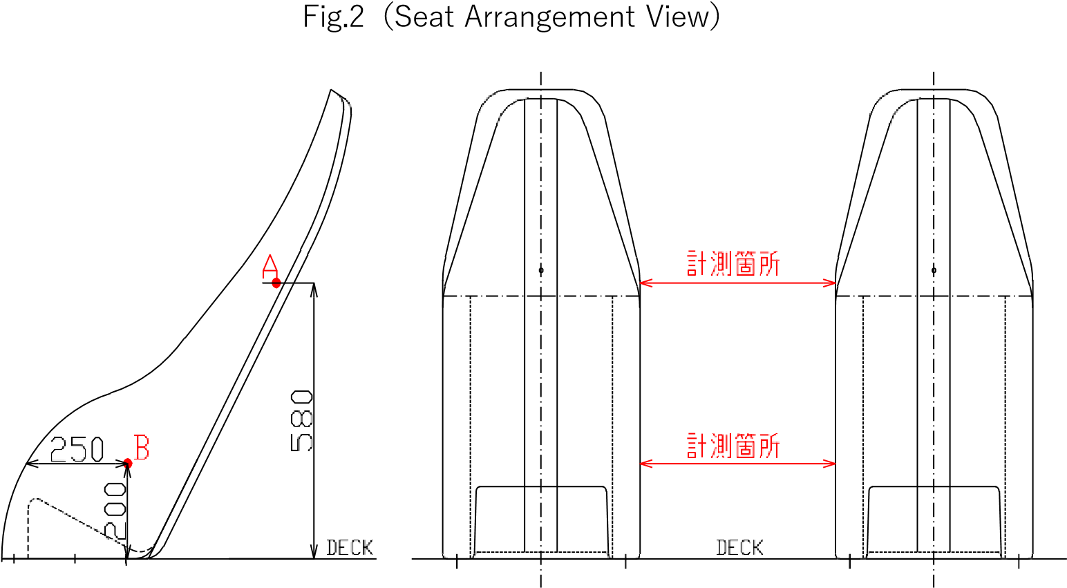
In addition, the passage width at each location is measured at Points A and B, as shown in Fig. 2 (Seat Arrangement View).
Note: Since a pipe ladder is installed on the floor at location ①, the measurement point B is taken at the top surface of the pipe ladder.
2,Locations with Insufficient Passage Width
The locations do not meet the required standard of 480 mm are positions ① and ② in Fig. 1 (Plan View), which are short by approximately 5–10 mm, and position ⑤, which is short by approximately 70–90 mm.
Attachment2
Items for seat adjustment
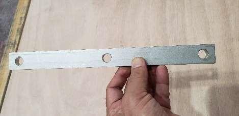
1,Seat Tilt Adjustment Brackets
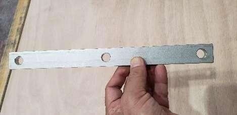
3t spacers × 10 pcs
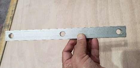
Used for adjustment at locations ① and ② in Attachment 1, Fig. 1 (Plan View).
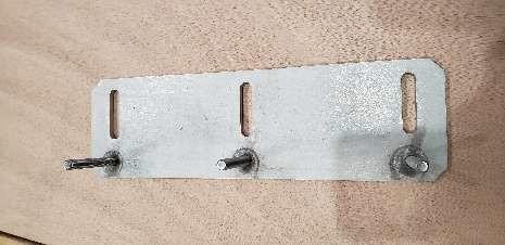
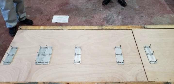
2,Seat Position Adjustment Brackets
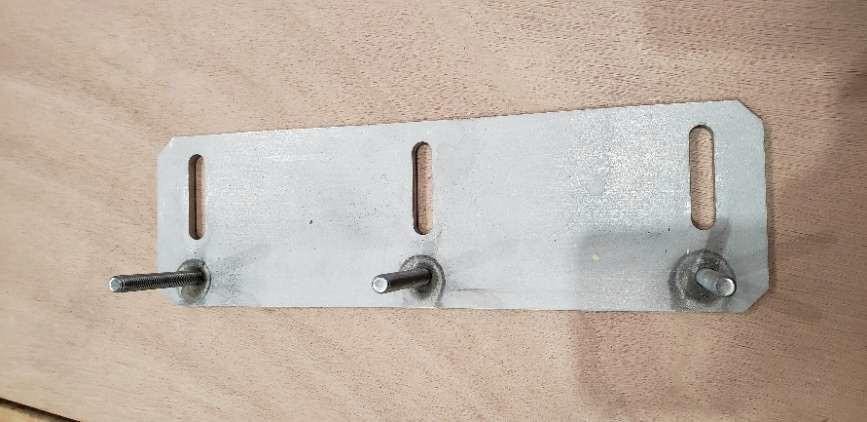
Seat adjusters × 6 sets
9t spacers × 6 pcs
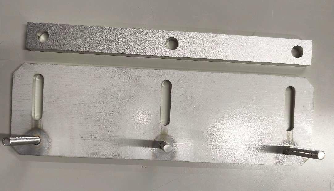
Used for adjustment at location ⑤ in Attachment 1, Fig. 1 (Plan View)
3,Installation Bolts and Nuts
M8 nuts × 20 pcs (including 2 spare pcs)
M8 flat washers × 20 pcs (including 2 spare pcs)
M8 spring washers × 20 pcs (including 2 spare pcs)
Instruction for the passage way width adjustment. |
Instruction was Noted by Class NK, 24 DEC 2025 |
Lifeboat FF-65 type |
Work the passage way width adjustment. name |
From AFT Applicable 1st aisle location 2nd aisle 5th aisle |
Nishi-F Co.,Ltd. |
Item
and
tool
Item
Seat
adjuster
×
6
Spacer
(
thick
type
9
t
)
×
6
Our
supply
Liner (thin type 3t)
×
10
pcs
8
+
)
2
pcs(extra
SW
:
Spring
washer
Nut,
sw,
fw
pcs/each
20
FW
:
Flat
washer
NT
:
Nut
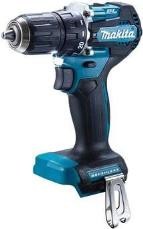
Drill
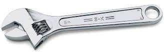
Adjustable
wrench
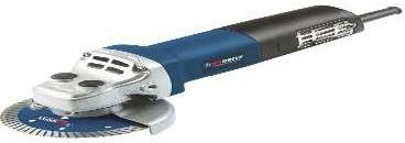
Grinder
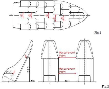
Applicable
aisles
and
Passage width measurement
points
5th aisle work procedure | |
1, measurement confirmation (current situation) | |
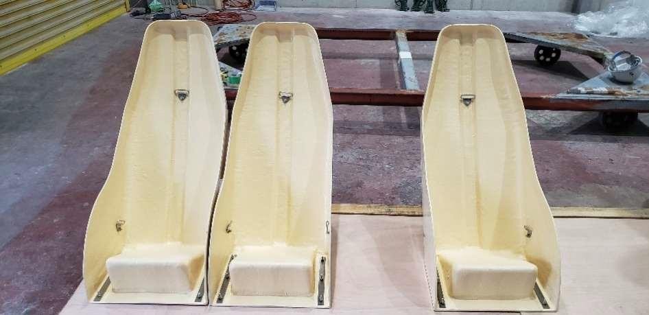 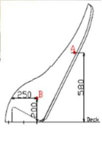 1 2 3 Measure point side view  | Seat width Measure point 580mm from the deck ※Measure points was mentioned on our attached FIG.1. |
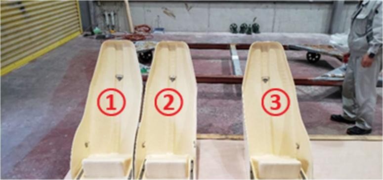 | 2-1, Seat removal Content Remove all three seats after measuring the passage width. |
 3 2  | 2-2, Seat removal Content Left pic shows removed seat deck. |
5th aisle adjustment procedure | ||
| 3-1, Installing the seat Adjuster Content Prepare the left pic seat adjuster. 6pcs | |
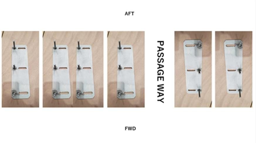
  2 | 3-2, Installing the seat Adjuster Content As shown in left pic, Place the seat adjuster. *The placement directions of ① and ② are reversed. | |
| 3-3, Installing the seat Adjuster Content As shown in left pic, Install the seat adjuster in order of FW → SW → NT. *fix the seat adjuster tighten. | |
5th aisle adjustment procedure | |
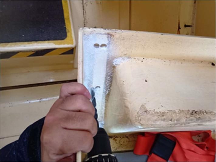
| 3-4, Installing the seat Adjuster Content Cut all original bolts above from the nut. *Cut the bolts as closely as possible to the nuts, it may touch the seat bottom when re-install the seat. *Protect threads by taping. |
| 3-5, Installing the seat Adjuster Content Losen all nuts a little to be able to the seat adjuster slide free. |
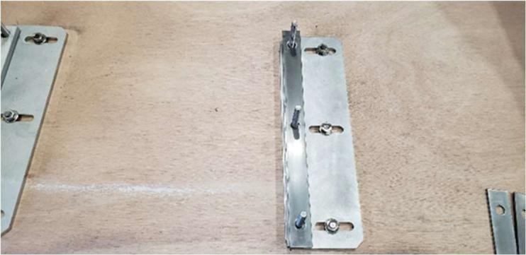 | 3-6, Installing the seat Adjuster Content Place the spacer onto the seat adjuster (Red marked) |
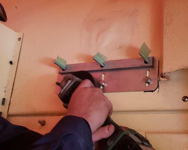
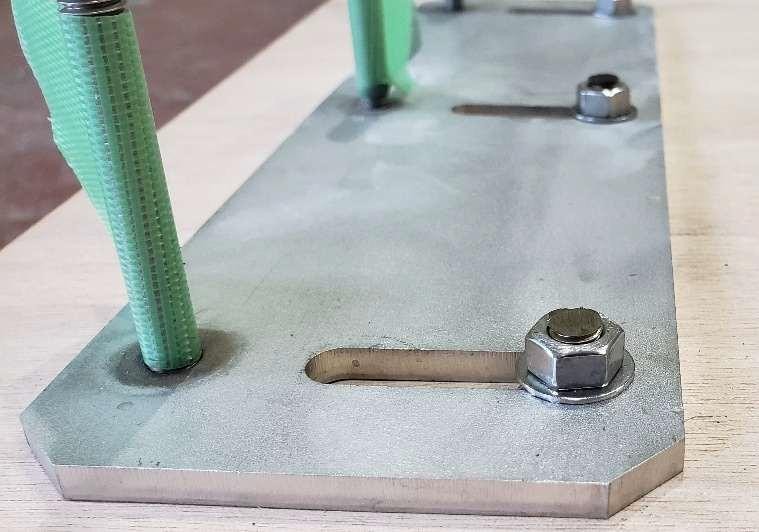
5th aisle adjustment procedure | |
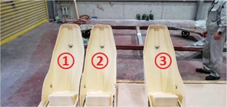
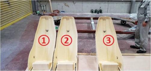
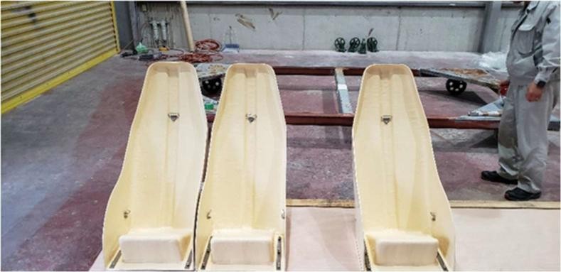 1 3 | 4-1, Temporarily assembled. Content Install seats in order of ① → ③ |
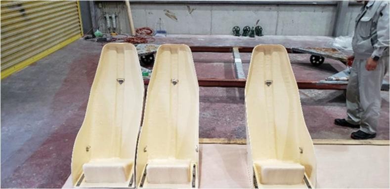  | 4-2, Temporarily assembled. Content Slide each sheet all the way up to the outer surface wall. |
| 4-3, Temporarily assembled. Content Install seat ② , Make sure that there’s no clearance between seat ①and②. |
5
th
aisle
adjustment
procedure
5
-
,
1
Re
-
measurement
Content
Re
-
measure
the
same
point to the step 1.
Case
1
,
More
than
mm
480
→
End
of
adjustment.
Go
to
7
-
1
Case
2
Less
than
mm
480
→
Go
to
6
-
1
6
-
1
, adjustment the
seat
vertical
angle.
Content
Remove
seat
③
,
Place
a
spacer
to
adjust
seat
vertical
angle.
Red
(
marked)
6
-
, adjustment the
2
seat
vertical
angle.
Content
Re
-
install
the
seat
and measure the
width again.
Case
1
,
More than 480mm
End
of
adjustment.
→
Go
to
7
-
1
Case 2
Less
than
mm
480
→
Go
to
6
-
3
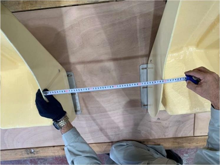
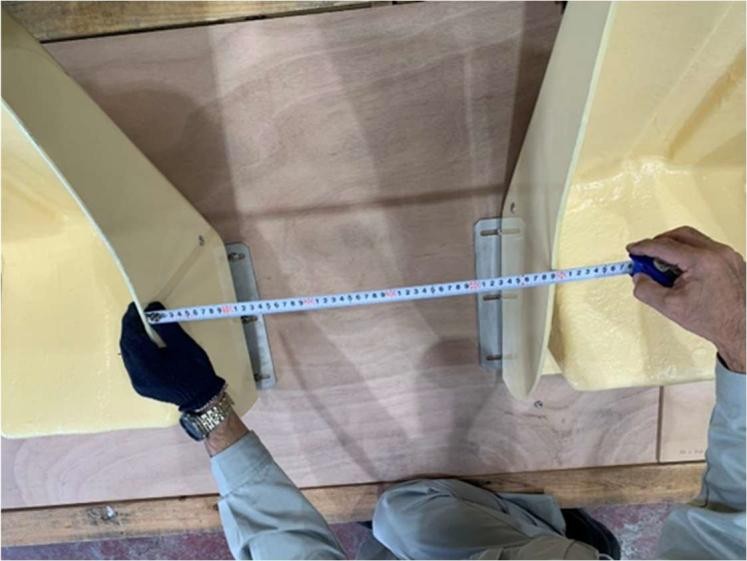
5th aisle adjustment procedure | |
 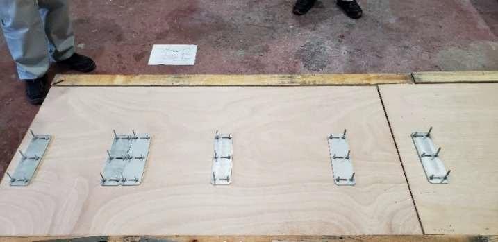  | 6-3, adjustment the seat vertical angle. Content Remove seat ②, Place a spacer to adjust seat vertical angle. (Red marked) |
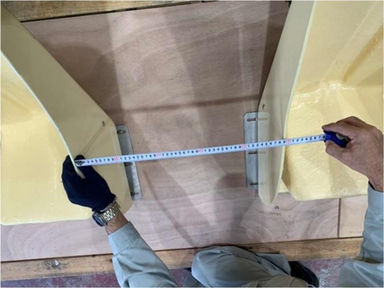
| 6-4, adjustment the seat vertical angle. Content Re-install the seat and measure the width again. Case 1, More than 480mm End of adjustment. →Go to 7-1 Case 2 Less than 480mm →Please contact us. |
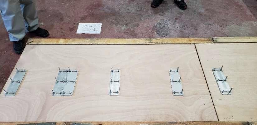
| 7-1, seat removal Content Carefully remove all seats not to move seat adjuster. |
5th aisle adjustment procedure | |
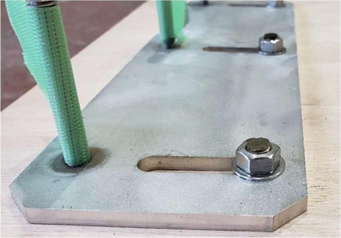 | 8-1, Final fixing of the seat adjuster. Content Tighten all seat adjuster fixed bolts (Red arrowed) |
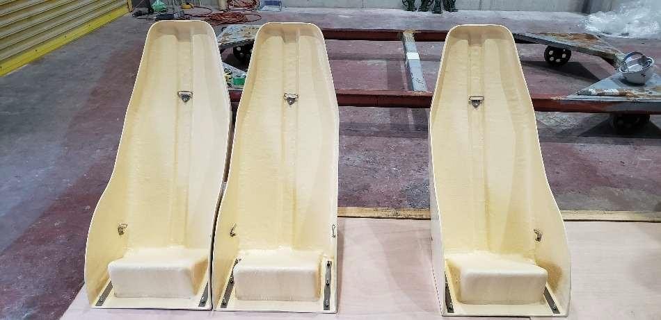 1 2 3 | 9-1, Final fixing of the seat Content Install all seats in order of ① → ② → ③ Tighten all seat fixed bolts. |
1st, 2nd aisle adjustment procedure | |
| 1, Measurement confirmation (current situation) Seat width Measure point 580mm from the deck |
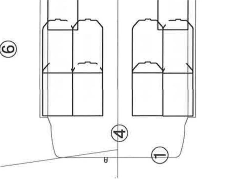 | 2, Seat removal Content Remove four aisle side seats (Red marked) |
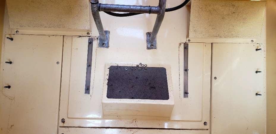 | 3, adjustment the seat vertical angle. Content Install one 3mm spacer only in exist bolts at both seats passage side, |
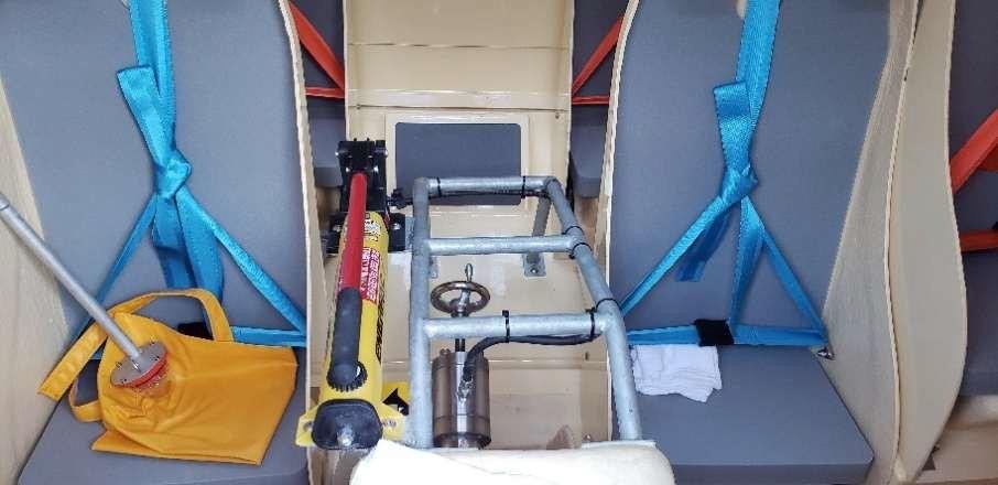
6th ,7th aisle adjustment procedure | |
| 4, Installing the seat Content Put the seat back and measure the width again. Case 1, More than 480mm End of adjustment. |
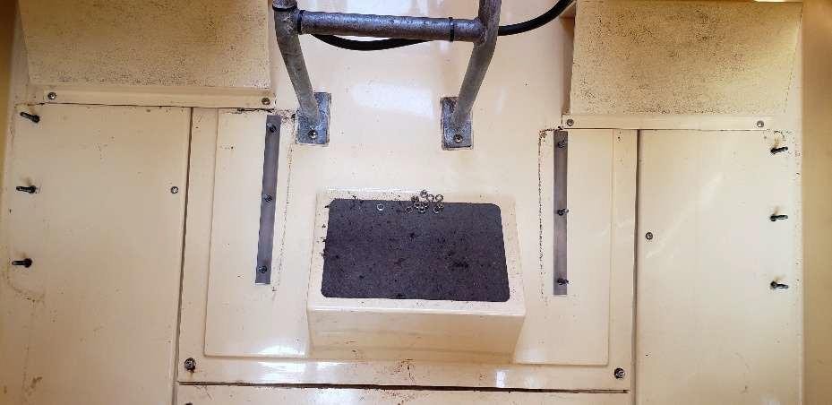 | 4, Installing the seat Content If further adjustment is required, remove seats again and add one more spacer. Then measure again. Installing two spacer is maxum. |
| 4, Installing the seat Content Put the seat back and measure the width again. Case 1, More than 480mm End of adjustment. |
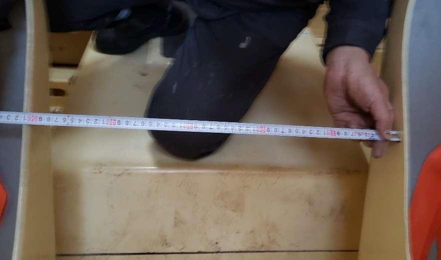
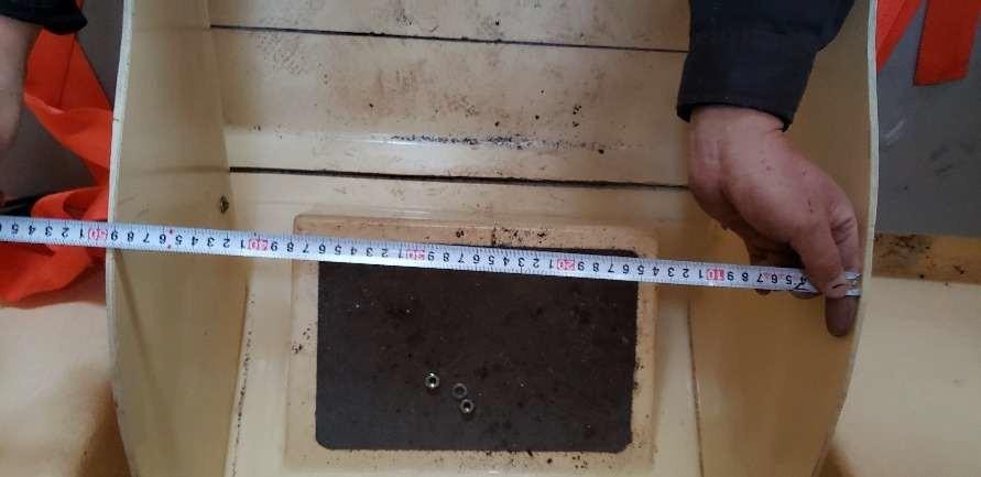
6th ,7th aisle adjustment procedure | |
| 5, Seat modification Content If further adjustment is required, make all bolt holes in the seats into slotted holes. |
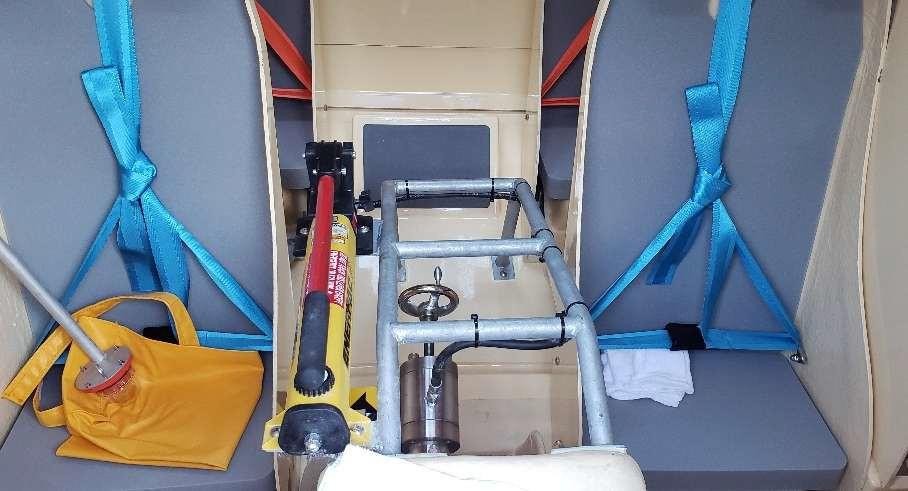 | 5, Seat modification Content Put them back. Push the seats to the wall side in order to make the passage way wider. Measure the width again. |
金具送付先連絡書 Confirmation form for sending countermeasure parts | 別紙 3 |
株式会社ニシエフ
NISHI-F CO.,LTD.
対策部品に付き、ご指定地に送付させていただきます。お手数かとは存じますが、下記表に部品の送付先をご記入の程お願いいたします
Regarding the replacement parts, we will send them to the designated location.
We apologize for the inconvenience, but please fill in the shipping address for the parts in the table below.
貴社名 Company name | |||
ご担当者様名 Person in charge | |||
船名Vessel name | 送付先住所 Consignee address | 電話番号 Tel | 担当者様 PIC |
荷姿(1艇分):幅 315×奥行 225×高さ 165 ㎜ 重量 13 ㎏ 材質:SUS304 | |||
NISHI-Fco.,ltd.
4238AWANO HOHOKU-CHO SHIMONOSEKI YAMAGUCHI JAPAN
TEL:+81-83-785-0126 FAX:+81-83-785-0356 E-mail: nfas@nishi-f.com